Wednesday, 6 September 2017
0 to 345 in 3mins. All my builds to date 6thSeptember2017
I took some time recently to hunt out pictures of all my builds. I found most of them in various places, old cloud storage, emails, PMs stuff like that. I managed to get photos of pretty much all of my builds. I'll add in the holes as I can. Looking back at old builds is great. It's great to see how far I have come with my builds.
Bring on the next 345!!!
Wednesday, 23 August 2017
Designing a better 3PDT Daugther board
--------------------------------------------------------------------------------------------------------------------------
THESE PCBs ARE NOW AVAILABLE TO ORDER FROM DIRTYPCBS!!!
--------------------------------------------------------------------------------------------------------------------------
3PDT Utilty - Panel of 4 Daughter boards x 10 (minimum order)
3PDT with LED Ring - Panel of 4 Daughter boards x 10 (minimum order)
Every pedal builder knows of the 3PDT stomp switch. It's pretty much the staple for true bypass effects. 3 Poles and 2 Throws. 2 of the poles are used for bypassing the effect and one of the poles for the indication LED. I'm not going to go into bypass methods as that's another whole rant. Many of the big name companies use them as well as most of the "boutique" (hate that word) pedal builders and most of the DIY home builder folks like myself. There are good ones and bad ones and in between ones. Usually you get what you pay for.
These switches are great..........but hand wiring them can be a drag and take up valuable time. Also on the cheaper ones if you have the iron on too hot and for too long you can melt the epoxy holding the switch contacts and basically ruin the switch. I'm all about making it easy for myself finding ways to improve my methods and speed stuff up. Heck in the last 4 months I made 105 pedals and this isn't my full time job. To make it easier and faster to solder up these guys some clever people have developed 3PDT daughter boards. For years I didn't use them, then one day I got some on a whim. I was forever sold on using them. Such a great time saver. There are now many pedal PCB shops that sell these little boards, delyk, Fuzz Dog, GuitarPCB to name a few.
A year or so ago I was just learning how to panalize in EAGLE and thought these would be a good starting point to make up some panels. Since then I have gotten about 400 or so 3PDT boards made up and I have been using them since them with great success.
I was having a think one day and decided to make a utility version of the beloved 3PDT daughter board. One that could be used for more than just bypass. Say for instance you have a pedal that you want to have 2 x gain settings on and a bypass on foot switches. I would have had to hand wire the gain pots to the switch and the bypass on a daughter board. Until now...
First of all I had to draw up the schematic. It has my Interlink part as previously seen in the blog. Also I had to make a special SMD part up for a bridging pad. Two small SMD pads with a 0.3mm gap between them so a blob of solder makes the connection. I just took a part from the sparkfun library and modified it to suit.
Once in schematic form I switched to the board and routed it. I like to keep nice big fat traces on the audio path and V+ rail where I can.
Why is this a better 3PDT board than others?
Setting up to use a switch is also very easy. Just don't bridge the pads. You can see in the picture below which pads the contacts of the switch end up on. This time and Dual colour LED can be hooked up to the three LED pads and indicate either switch state


THESE PCBs ARE NOW AVAILABLE TO ORDER FROM DIRTYPCBS!!!
--------------------------------------------------------------------------------------------------------------------------
3PDT Utilty - Panel of 4 Daughter boards x 10 (minimum order)
3PDT with LED Ring - Panel of 4 Daughter boards x 10 (minimum order)
Every pedal builder knows of the 3PDT stomp switch. It's pretty much the staple for true bypass effects. 3 Poles and 2 Throws. 2 of the poles are used for bypassing the effect and one of the poles for the indication LED. I'm not going to go into bypass methods as that's another whole rant. Many of the big name companies use them as well as most of the "boutique" (hate that word) pedal builders and most of the DIY home builder folks like myself. There are good ones and bad ones and in between ones. Usually you get what you pay for.
 |
| A typical 3PDT stomp switch |
A year or so ago I was just learning how to panalize in EAGLE and thought these would be a good starting point to make up some panels. Since then I have gotten about 400 or so 3PDT boards made up and I have been using them since them with great success.
I was having a think one day and decided to make a utility version of the beloved 3PDT daughter board. One that could be used for more than just bypass. Say for instance you have a pedal that you want to have 2 x gain settings on and a bypass on foot switches. I would have had to hand wire the gain pots to the switch and the bypass on a daughter board. Until now...
First of all I had to draw up the schematic. It has my Interlink part as previously seen in the blog. Also I had to make a special SMD part up for a bridging pad. Two small SMD pads with a 0.3mm gap between them so a blob of solder makes the connection. I just took a part from the sparkfun library and modified it to suit.
 |
| The Schematic |
Once in schematic form I switched to the board and routed it. I like to keep nice big fat traces on the audio path and V+ rail where I can.
 |
| PCB Routed out ready to panalize |
 |
| In Gerber viewer |
Why is this a better 3PDT board than others?
Because you can use it for True bypass OR as a DPDT switch with 2 x LED indication. And here is how.
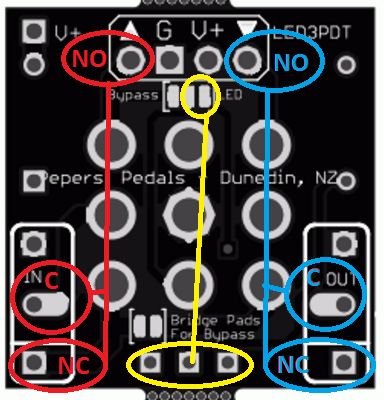
Setting it up for bypass is easy. Just chuck a big blob of solder on the two pads circled in the picture below. The bottom pad joins poles A and B together for the bypass part of the bypass. The top pads join the bypassed input signal of the effect to ground. I do it this way to ground the effect when not in use. for the LED in the configuration use the two pads that are circled at the top right of the board. The CLR and a Power Protection Diode are also installed on the board
 |
| Setup for Bypass |
Setting up to use a switch is also very easy. Just don't bridge the pads. You can see in the picture below which pads the contacts of the switch end up on. This time and Dual colour LED can be hooked up to the three LED pads and indicate either switch state
 |
| Setup as DPDT with LED indication |
So with that one done and dusted I thought why stop there. There have been a few pedals around with these new LED ringed 3PDT switches. They have a built in LED ring that lights up. They look quite good. I haven't used them on any of my builds but a fellow builder has. I was designing PCBs for this guy and thought hey why not do some daughter boards that you can use with these switches. So I did.


So sticking with the same formula I drew up some more PCBs
 |
| In Gerber viewer |
Just like above they are setup the same. Bridge the pads for bypass with the exception of a 3 way pad to wire to the LED
With the PCBs all drawn up I then put as many as I could onto a 100mm x 100mm panel.
 |
| For bypass |
 |
| For use as a DPDT with Dual LED indication |
My method of panalizing is probably the slowest but it works for me. What I do is make a copy of the .BRD file into another folder which severes the connection between schematic and board. I then draw 1.016mm or 40mil line on the milling layer for a milling cut. I also made a custom part of a row of 7 0.5mm hole to make the mouse bites. Once I'm happy with the milling lines and mouse bites on one of the boards I select the whole lot and copy it, Then I paste a copy and line it up with the original. Rinse and repeat to fill a 100mm x 100mm panel. I process the board in the CAM processor and then have a look at the gerber file. Adjust anything that needs adjusted and reprocess. You'll notice in the below screen capture of the board there are a mix of PCBs. 10 x 3PDT 2 x Miniature 3PDT and 4 x LED ring 3PDT . I'm going to do a post on how I panalize at some stage in the future. The boards are currently in production at DirtyPCBS
 |
| Panalized board put into the Seeedstudio gerber veiwer |
For anyone that is interested here is a dropbox link to my switch library PP-Switches
Here is what they look like in EAGLE. The outline is in the "TEST" layer so they don't appear on your processed Gerber
Here is what they look like in EAGLE. The outline is in the "TEST" layer so they don't appear on your processed Gerber


Wednesday, 16 August 2017
BOSS HM-2 Modding....This time a Blend control.
I love messing around with HM-2s. This is a super simple mod and very useful. Adding a clean blend to the mighty HM-2

I have done this enough times to have a modified schematic drawing with where to add/cut stuff in.
First thing to do is open up the pedal and move the wires around and drill a hole for the pot. I use a 9mm pot as there isn't much room in there.
Now I take my 9mm pot and put some 80mm (approx.) fly leads on it and then mount it into the hole, put the nut and washer on and tighten.
Next I build up my little blend PCB. I have designed a PCB for adding to any circuit to add a clean blend. As long as they are in phase it works great for only a handful of components. I don't sell this PCB it's just for me. Alternately if you want to do this mod you can use this. It's a vero layout of the same circuit I have made a PCB of. I'm not taking credit for the circuit it's not mine. I do however use a 100N cap instead of a 10N as I found it sounds better.
So now with my PCB made and the 9mm blend pot installed all I need to do is wire it into the HM-2. To do this I need to cut 1 track on the HM-2 PCB. This track is after the volume but before the FET bypass switching system (as labelled on the schematic above).
Now with the trace cut I can start soldering wires onto the main PCB. Two wires from the 9mm Blend pot, Pin 3 and Pin 2 go onto where the cut trace is. Pin 3 goes to Pad #8 and Pin 2 goes to the other side of the cut trace which connects to C32.


Time to connect up the rest of the wires. To do this I have to find the input to the effect on the effect side of the FET for the bypass switching system. Q4 is the FET doing the switching. I need to solder the send wire to the daughter board to somewhere at the junction of Q4, C6 and R16. Blend Pin 1 connects to the daughter board after the 10uF cap. V+ of the daughter board connects to the main board at Pad #2. GND of the daughter board connects to the main board at Pad #3.
With everything now soldered in it;s time to test the mod. Tested it with no issues. Now I need to secure the daughter board with a bit of the old hot snot glue, attach a knob to the pot, put it all back together and send it off the customer.
So that's how you mod an HM-2 to have a blend control. This is a pretty easy mod to do even for a beginner. If you have any questions or comments add them below

I have done this enough times to have a modified schematic drawing with where to add/cut stuff in.
 |
| Modified Schematic |
First thing to do is open up the pedal and move the wires around and drill a hole for the pot. I use a 9mm pot as there isn't much room in there.
 |
| Guts and hole drilled |
 |
| HOLE! |
 |
| Wires soldered on |
 |
| Mounted |
 |
| My little PCB |
 |
| All ready to go |
 |
| Locate the trace at pad #8 |
 |
| Trace cut with Exacto knife. |


Time to connect up the rest of the wires. To do this I have to find the input to the effect on the effect side of the FET for the bypass switching system. Q4 is the FET doing the switching. I need to solder the send wire to the daughter board to somewhere at the junction of Q4, C6 and R16. Blend Pin 1 connects to the daughter board after the 10uF cap. V+ of the daughter board connects to the main board at Pad #2. GND of the daughter board connects to the main board at Pad #3.
 |
| Start connecting daughter board |
 |
| Find Q4 |
 |
| Power wires soldered on and location of Q4 Traces on PCB |
 |
| Ready to test |
With everything now soldered in it;s time to test the mod. Tested it with no issues. Now I need to secure the daughter board with a bit of the old hot snot glue, attach a knob to the pot, put it all back together and send it off the customer.
So that's how you mod an HM-2 to have a blend control. This is a pretty easy mod to do even for a beginner. If you have any questions or comments add them below
 |
| Testing |
 |
| Ready to send. |
Saturday, 29 July 2017
Testing my PCBs easily
 |
| My custom part. IN GROUND V+ OUT |
 |
| Pin header, Vero scraps and a bulldog clip |
 |
| Finished clamp |
 |
| Mouth open |
 |
| Clamped onto the PCB |
 |
| Clamped on to the PCB |
So the clamp works pretty well. By using big grunty solder blobs on the pin header they make good contact with the pads. They took some adjusting to get right. I've checked this with a multimeter on the resistance scale and got readings between 0.2Ω and 0.4Ω on all 4 points back to spots on the PCB. Will test it out with an amp when I get a chance. The beauty of this thing is it will work on all my PCBs that I get made up so I can test quickly before boxing up.
Thursday, 20 July 2017
BOSS HM-2 Mod. Make it work on a 9v Power Supply
I recently scored one of the legendary BOSS HM-2 MIT beasts. I got in in an auction on eBay saying it was faulty. The description was along the lines of "works with a battery but not a power supply". I thought hey I know what that is!!


Boss have this ridiculous thing where they made you buy only BOSS power supplies back in the day. They called it ACA. Essentially they set up the pedal to work from a 12v supply by adding a resistor and a diode in series with the supply.
Here is a close up of the section that I need to do the mod.


I want to keep this as close to original as possible So instead of removing D1 and R2 and putting a link in I will just put a solder blob across wire 4 and wire 5


With the solder blob in place the mighty HM-2 will now run from a 9v supply perfectly. This mod can be applied to any BOSS ACA style pedal. If you are going to do this mod make sure that you confirm the correct components and wires.


Boss have this ridiculous thing where they made you buy only BOSS power supplies back in the day. They called it ACA. Essentially they set up the pedal to work from a 12v supply by adding a resistor and a diode in series with the supply.
 |
| HM-2 Schematic |
Here is a close up of the section that I need to do the mod.


I want to keep this as close to original as possible So instead of removing D1 and R2 and putting a link in I will just put a solder blob across wire 4 and wire 5


With the solder blob in place the mighty HM-2 will now run from a 9v supply perfectly. This mod can be applied to any BOSS ACA style pedal. If you are going to do this mod make sure that you confirm the correct components and wires.
Wednesday, 12 July 2017
Changing Potentiometer Shafts/Wafers
As a busy hobby pedal builder (300+ builds to my name) I buy a lot of pots.
I buy most of my pots from Tayda Electronics. They are alpha pots which are pretty good. I've ad no issues with them in the 6 years I've been building. They are well constructed and come with a handy little dust seal. The only issue I have from time to time is getting the right value with the style of shaft. I was building a Hot Cake clone and it called for a C50K pot (anti-log) I had some but they had spline and split shafts on them. I wanted to have a round shaft so I could put MXR style fluted knobs on them.
I set up my phone and recorded a short video of me swapping the shafts over. If you don't like loud angry music turn the volume down. I don't do any talking in it ( I have a terrible radio voice).
It's very simple with the right tools. I use an arbor press but it can be done in a vice too. I don't actually have a vice but I find it easier in a vice than the press.
That's pretty much it. I plan to design and build a jig to make this easier at some stage. For now this works for me.
 |
| My bulk pot storage |
 |
| My everyday pot storage |
I buy most of my pots from Tayda Electronics. They are alpha pots which are pretty good. I've ad no issues with them in the 6 years I've been building. They are well constructed and come with a handy little dust seal. The only issue I have from time to time is getting the right value with the style of shaft. I was building a Hot Cake clone and it called for a C50K pot (anti-log) I had some but they had spline and split shafts on them. I wanted to have a round shaft so I could put MXR style fluted knobs on them.
 |
| I need the round smooth shaft on the C50K |
I set up my phone and recorded a short video of me swapping the shafts over. If you don't like loud angry music turn the volume down. I don't do any talking in it ( I have a terrible radio voice).
It's very simple with the right tools. I use an arbor press but it can be done in a vice too. I don't actually have a vice but I find it easier in a vice than the press.
- Remove the back by lifting the tabs with a pair of pliers or any other tool will do.
- Place the pot upside down on the press into a sleeve so the shaft can move freely. I use a discarded linear bearing off my 3D printer but anything can be used.
- Using something skinny press down on the centre of the shaft. In the video I used the closest thing I could find which was a little phillips screwdriver, again anything smaller than the small shaft is fine. It wont go all the way down and out, the rest I pull apart by hand. This also helps make sure I don't drop/loose any bits.
- Swap the wafers (the flat bit with the carbon track on it) over onto the shaft that is desired and grab a plastic wiper wheel.
- This is the tricky bit. It takes a bit of practice and I've broken plenty of wiper wheels trying. You have to hold the pot and wiper and line up the small shaft on the pot to the wiper wheel. They are shaped like two D's back to back. Press it a little bit and check it. If it's no good re-position it and try again. If it's good make sure the wafer is lined up on the little locating pins and then press it all the way home.
- Spin the pot so the stopper lump on the wiper wheel is at the top and fit the back back onto the pot.
- Repeat for the other pot.....if you want to. I have a big box of pot bits that I haven't put back together
That's pretty much it. I plan to design and build a jig to make this easier at some stage. For now this works for me.
Friday, 12 May 2017
PPSS:6 - Another update
Another update on my switching system named PPSS:6. The first prototype was successful but a pain to build so I've redesigned it. Spent a fair amount of time redesigning the PCBs to be more modular. Went away from using the LED driver chip and used only 74hc595 shift register ICs. Made a main board with box style connectors for pre-made leads. Made a Relay/Jack PCB to board mount all the jacks and relays. This allows for much faster and easier assembly. Also made a LED PCB module for the same reason. Also made a faceplate panel and badge. This is all on a 100mm x 100mm PCB from Dirty PCBs (great cheap amazing service)
 |
| The PCB panel |
 |
| Making sure it all fits together |
 |
| All soldered up and ready to go |


 |
| It all fits |
 |
| To avoid the wonky holes that I had last time I used my CNC mill to pilot drill all the holes in the front panel |
 |
| Pilot holes nice and straight |
 |
| Faceplate |
 |
| More drilling completed and faceplate in place |
 |
| All the LEDs lined up |
 |
| 3D printed brackets that mount the PCB to one of the switches |
 |
| This all fits!! Amazingly |
 |
| Fitting stuff in. The premade leads I have wouldn't take any solder. I had to crimp connectors on the ends of the leads so I could solder them onto the switches |
 |
| All mounted in and it all fits so well. |
 |
| Pretty much the finished product |
 |
| All LEDs and relays operational |
#include <Shifter.h>
#define SER_Pin 4 //SER_IN
#define RCLK_Pin 6 //L_CLOCK
#define SRCLK_Pin 5 //CLOCK
#define NUM_REGISTERS 3 //how many registers are in the chain
byte x;
//initaize shifter using the Shifter library
Shifter shifter(SER_Pin, RCLK_Pin, SRCLK_Pin, NUM_REGISTERS);
void setup() {
Serial.begin(9600); // Used to type in characters
} //Setup Loop
void loop() {
if (Serial.available()) {
while (Serial.available() > 0) {
x = Serial.parseInt();
shifter.setPin(x, HIGH);
shifter.write();
Serial.print (x);
}
if (x == 99) {
shifter.clear();
shifter.write();
}
}
} //Main Loop
Basically this bit of code allows me to have the PPSS:6 connected to my PC and I can use the serial plotter to send a number to it. It then takes that number and fires the output on the 74hc595 shift register IC. If I send "99" it turns all the outputs off.
I wrote a similar bit of code to test the inputs. In doing so I found that the two analogue inputs A6 & A7 that I was using as digitals don't work as digitals highlighted in this article. A couple of hack wires later and some code changes and I had all the inputs running.
I have a pretty solid version of the code running but it still needs small changes. Thinking of adding a few extra things to the PPSS:6. I have 2 spare relay outputs so I think I'll use one as an amp switch and the other as a mute switch. I'll make up another PCB with these things mounted on it as well as the input buffer and tuner send jack. Thinking of using switch hold to turn on these features. Press and hold switch 1 for mute press and hold switch 6 for amp switch.
That's pretty much where I'm up to with the project. I have a friend using the first prototype to see if there are any issues or bugs.
Subscribe to:
Posts (Atom)