Monday 24 April 2017

PPSS-6 : Pepers' Pedals Switching System 6. An update of progress on my switching system

So I've been doing some more work on my effects switching system that I have named PPSS-6. I boxed up the prototype and put it through it's paces. This took a fair bit of work and a whole lot of time.
Drilling template
All drilled....by hand. wonky holes and all

Parted out to check fits

Powder Coated black

Parting out.

More parting out

Most the guts done
All the guts in

Front shot

So with it assembled and running I shot a video of it working.

The modes are as follows:

Normal Mode - Each switch is linked to a single loop only. All loops are independent of each other
Channel Mode - An extension of Normal Mode. Channel mode can be assigned to any of the loops. I needs to be applied to 2 or more loops otherwise it is pointless. Channel mode allows the user to change from one loop to another with only one button press. For instance loops 1,2,3 are in channel mode, switch channel 1 on it will turn off either 2 or 3, switch channel 3 on it will turn off loops 1 or 2. Any combination of Normal and Channel modes can be setup in Normal.
Preset Mode - 6 programmable presets. Each switch can have any combination of loops assigned to it.

The green LEDs are the switch. The red LEDs are the loops. When switching from Preset mode to Normal mode non of the loops turn off instead the switch LEDs dedicated to the loop that are on will light up.


So that is the first prototype finished. I decided that assembly of this unit took far too long. So I have redesigned in. I will cover that in my next post. This one is getting too long.

Saturday 15 April 2017

Building a Booger Booster from start to finish

I had time today to build an order #225 a Booger Booster. It's an LPB-1 clone. I had a helper in the form of my 5 year old son Harper. This post will follow every step of the build process.

Any questions or comments are welcome.

First of all I need to sort out the layout, drilling template and graphics for the pedal. I do all my stuff in Inkscape (free and open source) with Pedal Builder's Vector Art Pack. Using a layer for each stage it very easy to design and export drilling templates and graphics ready to apply to the enclosure.
Each layer of the proposed design

With the pedal designed and ready to go it's time to export the images and print out the drilling template and waterslide decal. 

My laser printer. I use this for everything. Great printer.

I export my final graphics at 600dpi and print as "Labels". I use laser decal paper from Decalpaper Australia I use both clear and white. These decals I printed previously on another sheet with some other decals as the paper is expensive to waste.

Template and Decals
Now with the template and decals ready it's time to apply the template and head to the basement to drill the enclosure. I use masking tape to attach the template as it doesn't leave any sticky residue.
Template attached and holes centre punched
I use a 3mm-8mm Centre drill bit to drill as a pilot and for the pots and LEDs. 3mm LED or 8mm for bezel. 8mm for pots as it allows a little room to adjust. Them I drill out the rest of the holes to the correct sizes. 12mm for 3pdt, 12mm for DC jack, 9.5mm for jacks. After drilling I then deburr all the holes so all the sharp edges are gone and the decal wont catch on them when applying it.
About to drill.
Deburred all edges.
Alright now the enclosure is drilled, it's time to apply the decal. First I need to clean the enclosure before applying the decal. The enclosure is a pre-powder coated 1590A from Tayda. Unfortunately the enclosure had some black rub marks on it that needed to come off before applying the decal. I used some paper towels and toothpaste and it came up really good. Washed it off. Then using alcohol (uvex len cleaner) I cleaned the enclosure clear of any fingerprints or any other contaminates .

Toothpaste treatment

Washing off the minty fresh toothpaste

Super clean and ready to go

Now that the box is super clean it's time to cut out and apply the graphic. I use nice sharp (expensive) scissors to cut the decal and make sure i round the corners off so the decal doesn't lift. I use an old takeaway container for the decal bath. I use luke warm soapy water for my decals.
Trimming
Trimmed
Put into decal bath face down for about 5 seconds

Decal face up for abut 20 seconds. When it starts to move a bit it's ready to go
Applying the decal. I put a little bit of water on the surface of the box
just before I apply the decal
Decal on!
Carefully dab off surface water and push out any bubbles.
Trying hard not to move it too much. This bit can be tricky.

Add caption
Ok. So now I have to wait for the decal to dry so I can powder coat it. So while that's happening I'm going to do the vero board. It's a super simple one and LPB-1 EHX clone. I'm going to use the Tagboard Effects layout. The layout isn't right so I had to correct it on the fly. I've also added 100uf and 100nf power filter caps.
Selecting some vero from the scraps
Trim to size
My custom vero cutter that I built from a bolt a drill bit and some heatshrink
Add resistors
Caps
All components soldered in and vero ready to go
Vero board ready and decal dry (mostly) it time to proceed to powder coat the box with clear power to seal on the graphic and protect it. I have a cheap and nasty powder coating system rigged up with a small air compressor. I run about 12PSI going into the gun. First I re-clean the enclosure and make sure there is no dust, fingerprints or anything on the box. Then I give it a pre-heat to about 50-70 DegC for a few minutes. I then apply the clear powder. Next is to place it into my modified bake oven to cure the powder. It needs 180DegC for 8mins to completely cure.
Decal dry

Pre heat and dry off the last of the decal

Hanging ready to coat

Powder coat system

Powder coat setup
Power Coating in action
Coated and ready for baking

8mins @ 180DegC

Baking in my modified oven
Air temp setting to get part temp right


Measurement
Done and cooling.
Next step is to part out the enclosure and put the guts in. I use my 3d printed pedal sockets to tighten up all the nuts to avoid marking/scratching the box.
Bits to go in

Cut off the silly tab

Tighten up the pot nut

Tighten up the stomp nut
Tighten up jack nuts

All guts in. Using a miniature 3PDT for this build.

All the hardware in time to start soldering parts in and do internal wiring. Starting with the LED. Then the ground wiring. Then signals
LED ready to go.

Interal wiring started
All internal wiring completed. (Mistake fixed with jack GND)
Board in

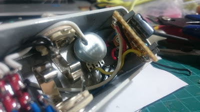
Transistor in socket ready for testing 
Almost done. It's assembled and ready for testing.
Behold the Booger Booster

Testing time.
And it goes. Right first time!!!! Time to put the finishing touches on. Add my internal label. Date. Trim and solder in the transistor.
Finishing touches
So that's how I built this little booger  #225. Now time for some glamour shots.