Sunday, 7 January 2018

Pepers' Pedals HM-Too Many Clones. Build your own BOSS HM-2 Clone

UPDATED 1-6-2018 - Minor Changes to build doc images. New Blend version coming soon
UPDATED 16-2-2018 - Drilling templates, EQ mods, Diode Mods

After many hours of perfecting and careful component selection and measuring of various crucial components I have finally finished my HM-2 Clone PCB.

I have aptly named it HM-Too Many Clones and it's a very very close recreation of the MIT and HM-300 I have here at home.

This PCB is available to everyone!! You can buy it straight from the fab shop in minimum quantities of 10.

Comes in 2 different versions Pots Up and Pots Down. The PCB itself comes with mods and 3PDT daughter boards too. So it's very flexible. Make sure you choose the right colour. I think it defaults to RED (they do look awesome in red).

BUY THE PCB AT DIRTYPCBS.COM


HM-Too Many Clones Build Documentation

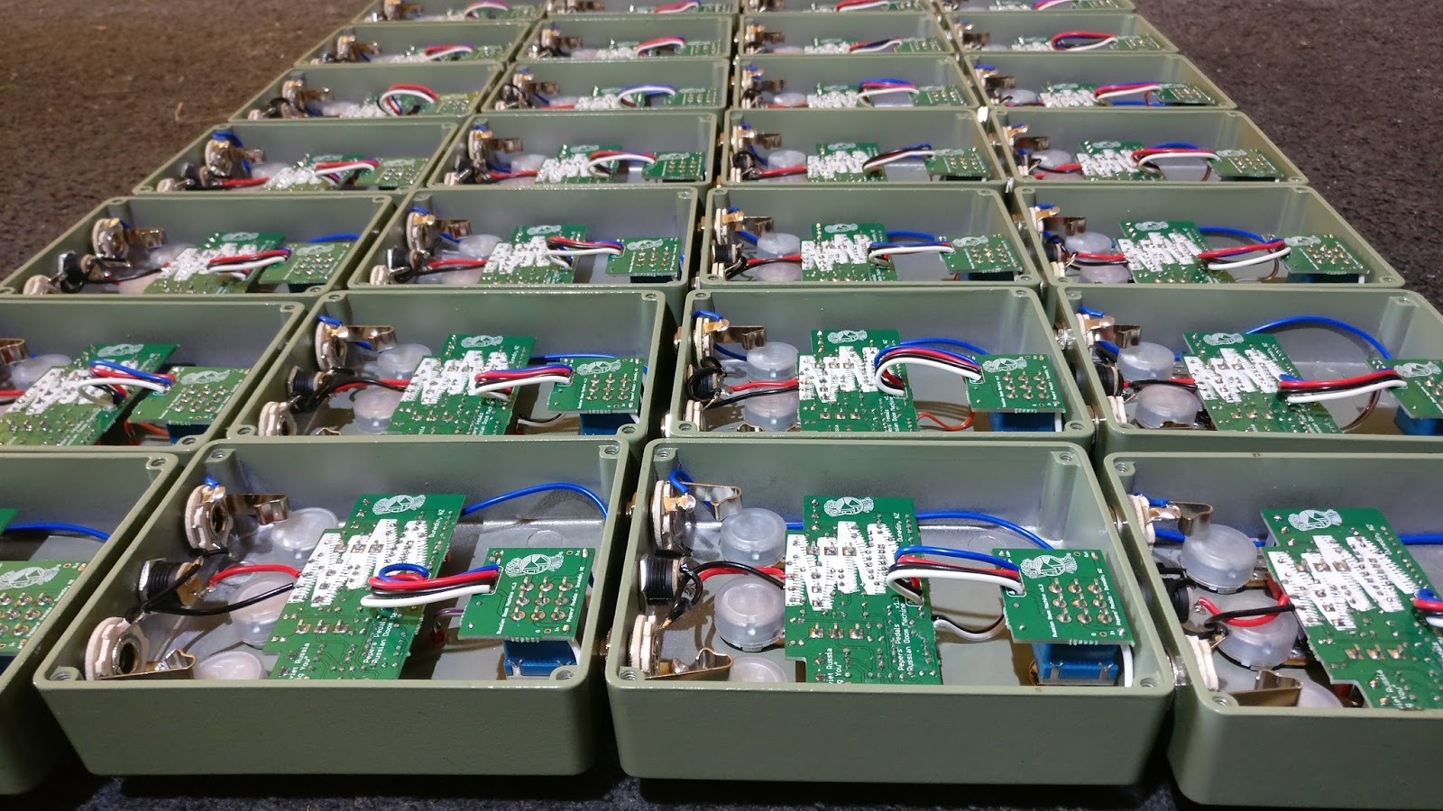
First of all the PCBS will come as a panel with all the elements connected together and if you have ordered from the above link you will get a minimum of 10x PCBS you may be lucky and get a few more, that's the beauty of the protopack. These smaller PCBS are joint together by something called a "mouse bite" a row of small holes. All these panels can be easily snapped apart to make the HM-TMC (Too Many Clones) into a few different versions.

HM-2 classic 4 knob
HM-2 with Mids control 5 knob
HM-2 with Mids and Blend control 6 knob
FX-56B Classic 4 knob verison
FX-56B with Mids control 5 knob
FX-56B with Mids and Blend control 6 knob


For more information on my 3PDT daughter boards have a look here. the 1N5817 can be installed either on the 3PDT board OR on the main board. Jumper the one that isn't used.


Now I guess we better go over the BOM. This is the BOM for the one that is in the used in the demo recording below. All component values are marked on the PCB. Values marked with an "*" are the components needed to exchange for the DOD FX-56B HM-2 clone and some are for other mods to come.


You don't necessarily need to use the components I have stated above that was my BOM for the build used in the recording. You are welcome to experiment with ICs transistors, diodes and cap types (be wary of tolerances on caps). There is no reason why you can't use TL072 Op-amps, LEDs for diodes and BC series transistors. I have found the FET buffer can be a J201, 2N5457 or 2SK30 (crossed legs) and all get basically the same sound. You can use 2n3904 and 2n3906 for the transistors too. I've found that the PNP transistor ideal hFE range is about 280-320, the NPN ideal hFE range is about 350-420. Once again experimentation is welcomed.


Wiring configuration for the 5 or 6 knob verison. If you want either just Blend or just Mids mods simply snap off the PCB you don't want and rearrange the wiring to suit.


Wiring configuration for the classic 4 knob HM-2 clone. DON'T FORGET TO BRIDGE THE SOLDER PAD

DOD FX-56B Mods

These are all the component changes required to change it from an HM-2 to a FX-56B


Clipping Diode Mods

By using a DPDT switch (ON-ON or even ON-OFF-ON) and different clipping diodes different flavours of distortion can be obtained. This is a drawing showing where to connect wires to the PCB to take off to switches to add clipping options.


Any combination of diodes or transistors can be used. It's totally up to you to experiment.

Gyrator EQ Adjustments

Have a little play with the EQ bands. 

Download my Gyrator EQ calculation spreadsheet HERE

The spreadsheet has all the HM-2 values already inputted.

Drilling Template

I have made up a drilling template to help with assembling this pedal into a box. The file is a .svg which is a scalable vector file. I use Inkscape to make these drawing and I recommend it is used to open this file. Inkscape can be found HERE.

I have set this up using layers so you just need to turn layers off or on as you need them

The template include all the versions and ideal setup

Download the drilling template HERE


Finished product

This is my completed build on PCB version 1.0. The new PCBs are a little bit better organised and have a few errors corrected on them.


This is what you want to hear. Results! This is my HM-2 clone played by my great friend Josh Hughes. He has absolutely blown me away with this demo clip. No video just recorded audio.


This is the setup he used for recording all the tracks on guitar and bass in the above demo.

The signal goes  Guitar -> NS-2 Loop Send- > HM-TMC -> MXR Fullbore metal -> NS-2 Loop Return -> 35W Pepers Pedals mini power amp. The pedals were used at the settings below. The Fullbore metal is used to simulate a slightly dirty amp channel and for some tone shaping. After talking with him the NS-2 is only to remove noise for recording purposes. The pedal is "as quiet as a mouse"


Any comments or questions on this build put them down below. I will constantly update this page with more mods and additional build instructions if they are needed.

Looking forward to seeing all the community builds come out!!

Thursday, 4 January 2018

Delay with Momentary/Latching switch + Tails

Everyone loves a good delay. This one was built for a long time customer one of my earliest customers to be precise.
He requested a delay he could hold his foot on and then let go of it and the delay trails off. I suggested that he add the option of being able to have it latching or momentary and also be able to switch the tails on or off. So here is what I come up with.

First of all I needed to work out how to do the switching in this. I decided to use my little Digispark module PCB I made a while back. I've used Digisparks in a few other projects. They are awesome and can be bought for less that the cost of an ATtiny85 the IC that is on the board. CRAZY HUH!!??. This PCB is v1.0 and has so many flaws so I had to hack it up to make it work. I wrote some small code that gave me inputs from a toggle and a stomp switch and outputs to a relay and dual colour LED.

The control goes like so:
Toggle UP - Latching relay and Green indication LED
Toggle DOWN - Momentary relay and Red indication LED

Digispark module installed

Next I needed to add the Tails module. I also have a PCB designed for this. It usually mounts onto a 3PDT switch. I can't take credit for the schematic I found it on the DIY Stompboxes forum. It's explained thoroughly in the post. It's a summing amplifier that mixes the tails back into the normal signal

Slackers Tails Schematic

Tails Bypass module PCB
Tails module installed
Now that the tails module was in it was time to mount the delay board in. It's just a boring PT2933 based analogy sounding digital delay board. I call it the Delays Ahead.

Everything is in. Ready to test.

Now it's time to test it and make sure the switching and delay works as it should

Powers up ok

Latching
Momentary

After fixing a few issues in the code it was away. Worked perfectly. Foot on the switch with the toggle down and it gives delays until foot is lifted off and then trails off until there are no more repeats. Toggle up works as latching. Second toggle enables and disables the tails.

--------------------------------------------------------------------------------------------------------------------------

So that pedal was send out to it's owner and he was very pleased with the outcome. A few months past I decided that I should remove the toggle to change modes between latching and momentary by just using the switch. I wrote some new code and tried it out on my test Digispark module. I've developed this switching for a new chaos delay I'll be working on in 2018. If you aren't familiar with my Chaos Delay it is a PT2399 delay with oscillation based on the Rebote 2.5 circuit.

So with this new switching method I'll be able to use the delay for momentary like the above pink delay and also use the switching for the "Chaos" mode where it enables the self oscillation.

Click = Latching click on/off
Hold =Momentary. While being held output is on. Once switch is let go output is off.

Keep an eye out for projects with this switching method in them.


Sunday, 3 December 2017

AB utility box : A new approach

So I've been designing / building this thing off and on for about a year now (mainly off haha). New PCBs arrived the other day, this thing is up to v1.4 (me making stupid errors on the boards and also not understanding how the particular attiny85 module works). I made it all fit today and just wrote the code for it.
PCB Front

PCB Rear
OMG it actually all fits into a 1590B

This is an AB box that can do [A] and [B] or [A] or [B]. A and B means that both loops work off their respective footswitches [A] toggles [A] and [B] toggles [B]
A and B mode in with red LEDs
[A] or [B] means that [A] footswitch will turn on [A] and off [B] and [B] footswitch will turn on [B] and off [A].
One button change over.

Switching between loops
Switch between the two modes is done by holding down either button for 750ms ( I may adjust this)


This is built on a digispark attiny85 module. It's using Neopixel LEDs so it only needs 1 data pin for full RGB LEDs. The code is written in the Arduino IDE after installing all the necessary digispark drivers etc.

This came about more as a testing rig thing for my test board (quickly switch between pedals to compare A to B ). What do you reckon about the cyan and magenta LEDs? Took a bit of fiddling with values to get them looking nice.


Tuesday, 21 November 2017

Builds #379 - #408 Russian Doom Machines (RDMs)

I have been pretty busy lately. Far too buys to write blog post. I hit pedal number 400 in my last lot of RDMs. These green machines are becoming quite popular. This is my take on the classic Big Muff Green Russian. I have added a few little mods in the form of a diode clipping toggle switch and a mids scoop, flat, boost switch. Also I'm using higher gain transistors in the input buffer amplifier and the output recovery stage after the tone stack. Gives it that extra little bit of doom!

Anyway. Here is a bunch of pictures of me building 30 of them.
40 x RDM PCBS ready to fill with components
The 100NF caps used in RDMs. I recently used this image for a competition to win a RAD. It was a guess how many thing. 234 was the right answer.
40 x RDM PCBS parted out and ready to go into boxes
30 x 1590BB enclosures ready to be drilled
Cider and drilling

30 x drilled enclosures. About 1.5 hours work. I have a drilling template that makes a huge difference in speed.

More cider and off to the powder coat station.


Out Gassing in my custom modded oven
POWDER COATING + MIDNIGHT

Powder fully cured on the first one

Two Down
Applying Decals

That's a lot of decals. This took about 2 hours

All graphics on and powder coated clear for durability
Ready to start assembling
Hardware all mounted ready to drop boards in and solder up
Gut shots of the RDMs all ready to be tested
Another angle of the guts
The platoon of DOOM
Doom as far as the eye can see

Working vs not quite working. Sorting out the problem children

Putting the backs on
Dated and numbered


Putting the backs on with a little help from a minion. 2 years old and can already do righty tighty.

Heading to the for sale shelf. A big box of doom

BUY ME!!!!

Edit 22/11/2017

I have some of these left and they are available to purchase. They are $96.66USD + Shipping from New Zealand.

Email : peperspedals@gmail.com
Facebook : https://www.facebook.com/PepersPedals/
Instagram : @peperspedals #peperspedals