Saturday, 29 July 2017

Testing my PCBs easily

A while back I designed my own EAGLE CAD part for the interconnect between the 3PDT PCB and effect PCB a while back to make it easy to link up my boards.

My custom part. IN GROUND V+ OUT

To test my finished PCBs I would solder 4 leads on and wire the completed board into my test rig. I had a bit of a brain wave today and thought up of a device that could clamp over the pad that would be permanently wired to my test rig. I had a bit of a look around in my junk boxes and found a bulldog clip. The custom part I made has a 2.54mm spacing between pads which is the same as vero board. 
Pin header, Vero scraps and a bulldog clip
I glued the bits of vero to the inside of the bulldog clip with some loctite 401. Soldered the pin header at the end of one of the vero strips. Drilled 2mm holes on the other vero strip. Soldered some tails onto it and it's ready to go.
Finished clamp
Mouth open
Clamped onto the PCB
Clamped on to the PCB

So the clamp works pretty well. By using big grunty solder blobs on the pin header they make good contact with the pads. They took some adjusting to get right. I've checked this with a multimeter on the resistance scale and got readings between 0.2Ω and 0.4Ω on all 4 points back to spots on the PCB. Will test it out with an amp when I get a chance. The beauty of this thing is it will work on all my PCBs that I get made up so I can test quickly before boxing up.

Thursday, 20 July 2017

BOSS HM-2 Mod. Make it work on a 9v Power Supply

I recently scored one of the legendary BOSS HM-2 MIT beasts. I got in in an auction on eBay saying it was faulty. The description was along the lines of "works with a battery but not a power supply". I thought hey I know what that is!!


Boss have this ridiculous thing where they made you buy only BOSS power supplies back in the day. They called it ACA. Essentially they set up the pedal to work from a 12v supply by adding a resistor and a diode in series with the supply.
HM-2 Schematic

Here is a close up of the section that I need to do the mod.

I want to keep this as close to original as possible So instead of removing D1 and R2 and putting a link in I will just put a solder blob across wire 4 and wire 5


With the solder blob in place the mighty HM-2 will now run from a 9v supply perfectly. This mod can be applied to any BOSS ACA style pedal. If you are going to do this mod make sure that you confirm the correct components and wires.


Wednesday, 12 July 2017

Changing Potentiometer Shafts/Wafers

As a busy hobby pedal builder (300+ builds to my name) I buy a lot of pots.
My bulk pot storage
My everyday pot storage

I buy most of my pots from Tayda Electronics. They are alpha pots which are pretty good. I've ad no issues with them in the 6 years I've been building. They are well constructed and come with a handy little dust seal. The only issue I have from time to time is getting the right value with the style of shaft. I was building a Hot Cake clone and it called for a C50K pot (anti-log) I had some but they had spline and split shafts on them. I wanted to have a round shaft so I could put MXR style fluted knobs on them.
I need the round smooth shaft on the C50K

I set up my phone and recorded a short video of me swapping the shafts over. If you don't like loud angry music turn the volume down. I don't do any talking in it ( I have a terrible radio voice).

It's very simple with the right tools. I use an arbor press but it can be done in a vice too. I don't actually have a vice but I find it easier in a vice than the press.


  • Remove the back by lifting the tabs with a pair of pliers or any other tool will do.
  • Place the pot upside down on the press into a sleeve so the shaft can move freely. I use a discarded linear bearing off my 3D printer but anything can be used.
  • Using something skinny press down on the centre of the shaft. In the video I used the closest thing I could find which was a little phillips screwdriver, again anything smaller than the small shaft is fine. It wont go all the way down and out, the rest I pull apart by hand. This also helps make sure I don't drop/loose any bits.
  • Swap the wafers (the flat bit with the carbon track on it) over onto the shaft that is desired and grab a plastic wiper wheel.
  • This is the tricky bit. It takes a bit of practice and I've broken plenty of wiper wheels trying. You have to hold the pot and wiper and line up the small shaft on the pot to the wiper wheel. They are shaped like two D's back to back. Press it a little bit and check it. If it's no good re-position it and try again. If it's good make sure the wafer is lined up on the little locating pins and then press it all the way home.
  • Spin the pot so the stopper lump on the wiper wheel is at the top and fit the back back onto the pot. 
  • Repeat for the other pot.....if you want to. I have a big box of pot bits that I haven't put back together


That's pretty much it. I plan to design and build a jig to make this easier at some stage. For now this works for me.

Friday, 12 May 2017

PPSS:6 - Another update

Another update on my switching system named PPSS:6. The first prototype was successful but a pain to build so I've redesigned it. Spent a fair amount of time redesigning the PCBs to be more modular. Went away from using the LED driver chip and used only 74hc595 shift register ICs. Made a main board with box style connectors for pre-made leads. Made a Relay/Jack PCB to board mount all the jacks and relays. This allows for much faster and easier assembly. Also made a LED PCB module for the same reason. Also made a faceplate panel and badge. This is all on a 100mm x 100mm PCB from Dirty PCBs (great cheap amazing service)

The PCB panel
Making sure it all fits together
All soldered up and ready to go


It all fits
To avoid the wonky holes that I had last time I used my CNC mill to pilot drill
all the holes in the front panel
Pilot holes nice and straight
Faceplate
More drilling completed and faceplate in place
All the LEDs lined up

3D printed brackets that mount the PCB to one of the switches

This all fits!! Amazingly
Fitting stuff in. The premade leads I have wouldn't take any solder.
I had to crimp connectors on the ends of the leads so I could solder them onto
the switches
All mounted in and it all fits so well.
Pretty much the finished product
All LEDs and relays operational
I had to re-write all the code because of the removal of the LED driver IC and switched to 74hc595 shift register ICs. All the outputs and inputs have changed too. So to test the functionality of all the LEDs and relays I wrote a small bit of code and uploaded it to the Arduino NANO

#include <Shifter.h>
#define SER_Pin 4 //SER_IN
#define RCLK_Pin 6 //L_CLOCK
#define SRCLK_Pin 5 //CLOCK
#define NUM_REGISTERS 3 //how many registers are in the chain
byte x;
//initaize shifter using the Shifter library
Shifter shifter(SER_Pin, RCLK_Pin, SRCLK_Pin, NUM_REGISTERS);
void setup() {
  Serial.begin(9600);  // Used to type in characters
} //Setup Loop
void loop() {
  if (Serial.available()) {
    while (Serial.available() > 0) {
      x = Serial.parseInt();
      shifter.setPin(x, HIGH);
      shifter.write();
      Serial.print (x);
    }
    if (x == 99) {
      shifter.clear();
      shifter.write();
    }
  }
} //Main Loop

Basically this bit of code allows me to have the PPSS:6 connected to my PC and I can use the serial plotter to send a number to it. It then takes that number and fires the output on the 74hc595 shift register IC. If I send "99" it turns all the outputs off.

I wrote a similar bit of code to test the inputs. In doing so I found that the two analogue inputs A6 & A7 that I was using as digitals don't work as digitals highlighted in this article. A couple of hack wires later and some code changes and I had all the inputs running.

I have a pretty solid version of the code running but it still needs small changes. Thinking of adding a few extra things to the PPSS:6. I have 2 spare relay outputs so I think I'll use one as an amp switch and the other as a mute switch. I'll make up another PCB with these things mounted on it as well as the input buffer and tuner send jack. Thinking of using switch hold to turn on these features. Press and hold switch 1 for mute press and hold switch 6 for amp switch.

That's pretty much where I'm up to with the project. I have a friend using the first prototype to see if there are any issues or bugs.

Monday, 24 April 2017

PPSS-6 : Pepers' Pedals Switching System 6. An update of progress on my switching system

So I've been doing some more work on my effects switching system that I have named PPSS-6. I boxed up the prototype and put it through it's paces. This took a fair bit of work and a whole lot of time.
Drilling template
All drilled....by hand. wonky holes and all

Parted out to check fits

Powder Coated black

Parting out.

More parting out

Most the guts done
All the guts in

Front shot

So with it assembled and running I shot a video of it working.

The modes are as follows:

Normal Mode - Each switch is linked to a single loop only. All loops are independent of each other
Channel Mode - An extension of Normal Mode. Channel mode can be assigned to any of the loops. I needs to be applied to 2 or more loops otherwise it is pointless. Channel mode allows the user to change from one loop to another with only one button press. For instance loops 1,2,3 are in channel mode, switch channel 1 on it will turn off either 2 or 3, switch channel 3 on it will turn off loops 1 or 2. Any combination of Normal and Channel modes can be setup in Normal.
Preset Mode - 6 programmable presets. Each switch can have any combination of loops assigned to it.

The green LEDs are the switch. The red LEDs are the loops. When switching from Preset mode to Normal mode non of the loops turn off instead the switch LEDs dedicated to the loop that are on will light up.


So that is the first prototype finished. I decided that assembly of this unit took far too long. So I have redesigned in. I will cover that in my next post. This one is getting too long.

Saturday, 15 April 2017

Building a Booger Booster from start to finish

I had time today to build an order #225 a Booger Booster. It's an LPB-1 clone. I had a helper in the form of my 5 year old son Harper. This post will follow every step of the build process.

Any questions or comments are welcome.

First of all I need to sort out the layout, drilling template and graphics for the pedal. I do all my stuff in Inkscape (free and open source) with Pedal Builder's Vector Art Pack. Using a layer for each stage it very easy to design and export drilling templates and graphics ready to apply to the enclosure.
Each layer of the proposed design

With the pedal designed and ready to go it's time to export the images and print out the drilling template and waterslide decal. 

My laser printer. I use this for everything. Great printer.

I export my final graphics at 600dpi and print as "Labels". I use laser decal paper from Decalpaper Australia I use both clear and white. These decals I printed previously on another sheet with some other decals as the paper is expensive to waste.

Template and Decals
Now with the template and decals ready it's time to apply the template and head to the basement to drill the enclosure. I use masking tape to attach the template as it doesn't leave any sticky residue.
Template attached and holes centre punched
I use a 3mm-8mm Centre drill bit to drill as a pilot and for the pots and LEDs. 3mm LED or 8mm for bezel. 8mm for pots as it allows a little room to adjust. Them I drill out the rest of the holes to the correct sizes. 12mm for 3pdt, 12mm for DC jack, 9.5mm for jacks. After drilling I then deburr all the holes so all the sharp edges are gone and the decal wont catch on them when applying it.
About to drill.
Deburred all edges.
Alright now the enclosure is drilled, it's time to apply the decal. First I need to clean the enclosure before applying the decal. The enclosure is a pre-powder coated 1590A from Tayda. Unfortunately the enclosure had some black rub marks on it that needed to come off before applying the decal. I used some paper towels and toothpaste and it came up really good. Washed it off. Then using alcohol (uvex len cleaner) I cleaned the enclosure clear of any fingerprints or any other contaminates .

Toothpaste treatment

Washing off the minty fresh toothpaste

Super clean and ready to go

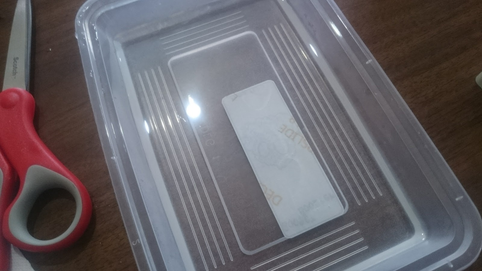
Now that the box is super clean it's time to cut out and apply the graphic. I use nice sharp (expensive) scissors to cut the decal and make sure i round the corners off so the decal doesn't lift. I use an old takeaway container for the decal bath. I use luke warm soapy water for my decals.
Trimming
Trimmed
Put into decal bath face down for about 5 seconds

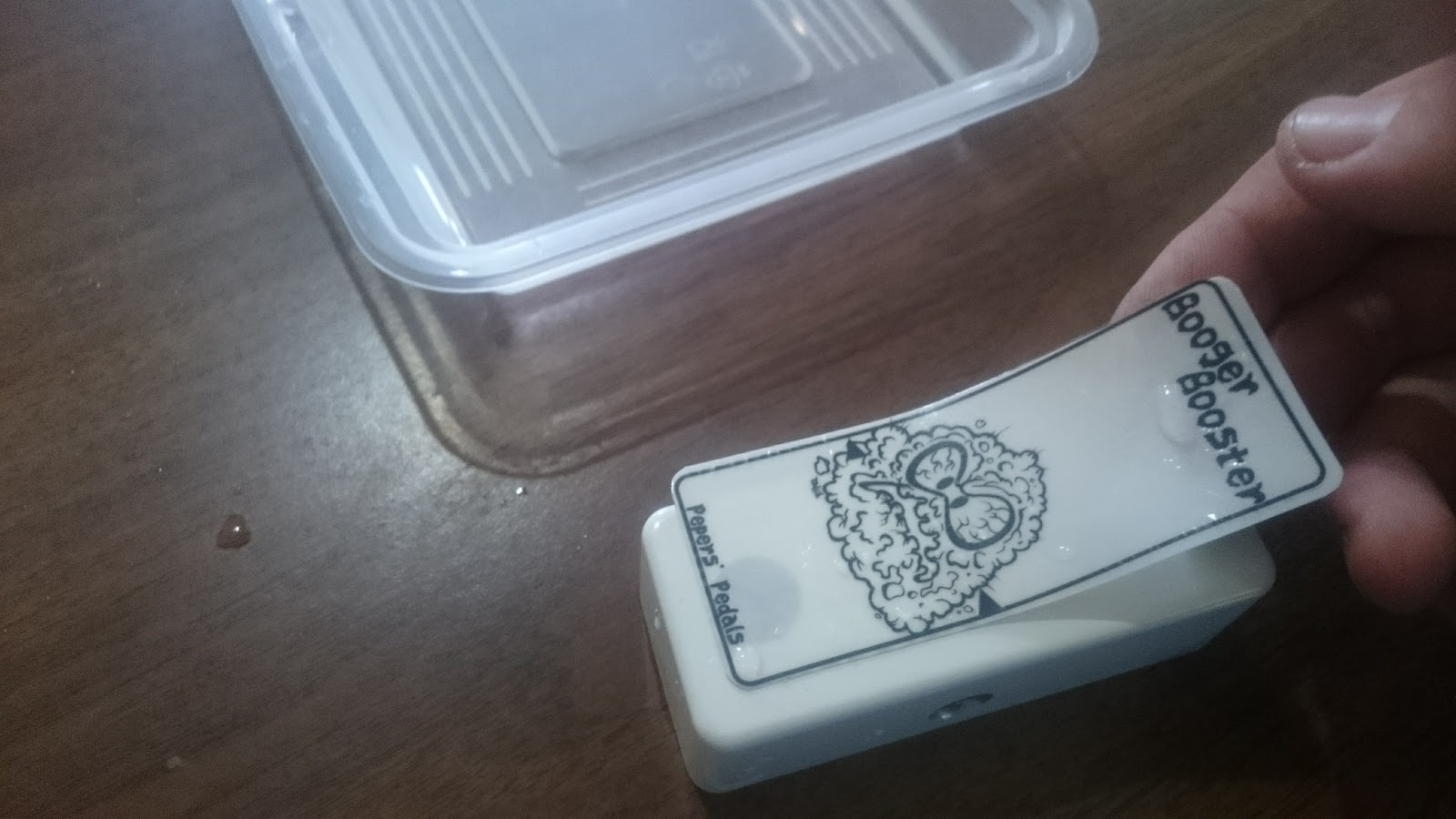
Decal face up for abut 20 seconds. When it starts to move a bit it's ready to go
Applying the decal. I put a little bit of water on the surface of the box
just before I apply the decal
Decal on!
Carefully dab off surface water and push out any bubbles.
Trying hard not to move it too much. This bit can be tricky.

Add caption
Ok. So now I have to wait for the decal to dry so I can powder coat it. So while that's happening I'm going to do the vero board. It's a super simple one and LPB-1 EHX clone. I'm going to use the Tagboard Effects layout. The layout isn't right so I had to correct it on the fly. I've also added 100uf and 100nf power filter caps.
Selecting some vero from the scraps
Trim to size
My custom vero cutter that I built from a bolt a drill bit and some heatshrink
Add resistors
Caps
All components soldered in and vero ready to go
Vero board ready and decal dry (mostly) it time to proceed to powder coat the box with clear power to seal on the graphic and protect it. I have a cheap and nasty powder coating system rigged up with a small air compressor. I run about 12PSI going into the gun. First I re-clean the enclosure and make sure there is no dust, fingerprints or anything on the box. Then I give it a pre-heat to about 50-70 DegC for a few minutes. I then apply the clear powder. Next is to place it into my modified bake oven to cure the powder. It needs 180DegC for 8mins to completely cure.
Decal dry

Pre heat and dry off the last of the decal

Hanging ready to coat

Powder coat system

Powder coat setup
Power Coating in action
Coated and ready for baking

8mins @ 180DegC

Baking in my modified oven
Air temp setting to get part temp right


Measurement
Done and cooling.
Next step is to part out the enclosure and put the guts in. I use my 3d printed pedal sockets to tighten up all the nuts to avoid marking/scratching the box.
Bits to go in

Cut off the silly tab

Tighten up the pot nut

Tighten up the stomp nut
Tighten up jack nuts

All guts in. Using a miniature 3PDT for this build.

All the hardware in time to start soldering parts in and do internal wiring. Starting with the LED. Then the ground wiring. Then signals
LED ready to go.

Interal wiring started
All internal wiring completed. (Mistake fixed with jack GND)
Board in

Transistor in socket ready for testing 
Almost done. It's assembled and ready for testing.
Behold the Booger Booster

Testing time.
And it goes. Right first time!!!! Time to put the finishing touches on. Add my internal label. Date. Trim and solder in the transistor.
Finishing touches
So that's how I built this little booger  #225. Now time for some glamour shots.