Music - The Accused - She's Back
Thursday, 16 February 2017
Drawing a Schematic in EAGLE CAD
I've been designing a new fuzz pedal with parallel paths and 2 different fuzzes. One side is a Meathead the other side is a Torn's Peaker. This is a short clip of me drawing up the schematic in EAGLE CAD. I'll breadboard/vero this up now and test it. Once I'm happy I'll do a PCB and another video of me designing the PCB.
Music - The Accused - She's Back
Music - The Accused - She's Back
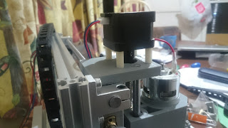
3d Printer printing Pedal Finger Sockets
This is my Prusa i3 printing out some Pedal Finger Sockets. Used an old Laptop camera mounted on the Z axis of the printer pointed at the print head.
A brief guide into tracing out a PCB to convert to schematic. b3k Clone
I haven't posted on here in a while. This is my little guide to tracing out a PCB.
I ordered a GUMA drive kit from Schalltechnik_04 which is a Darkglass b3k clone and before I assembled it I'd thought I'd give it a go tracing it out to produce a schematic. If you do want to build this pedal I highly recommend buying this kit. It's a very well laid out kit.
First thing I needed to do was get some super fine pointed tips for my multimeter. I ordered these from Aliexpress. The multimeter I have used for this is a APPA 62 and I've just used it on the continuity function.
I took a high quality photo of the PCB on my Sony xperia z3 and printed out a bunch of copies of it to help with the tracing.
I started to trace out the circuit with my multimeter. I removed the unnecessary parts that I didn't need to trace and blacked them out on my printed photos. The jacks and relay bypass was not needed to be traced. I started in a logical order starting with the power section. As I found connections I would draw them onto 1 printed age and cross out the component on another printed page I would also draw the schematic onto another piece of paper. After doing all the power stages I then went to the input and worked my way through the whole PCB. This whole process took me 20+ hours.
After I had my completed paper schematic I then drew it up in EAGLE CAD. Any CAD package is fine I'm just familiar with EAGLE.
This Schematic is verified. PCBs turned out great. Have since redesigned this layout to fit into a 1590B and also have the ability to make the b3k and vmt.
Update 18/2/2017
Update 20/2/2017
Updated the drawing as I had misplaced a resistor. R22 moved from above diode to between supply and pin 1 on the 4049.
Update 7/3/2018
I have made this effect quite a few times now. Schematic is verified. I've since made a new PCB that fits into a 1590B and can do the b3k and vmt by just swapping a few components out. I'm starting to make my own modifications on the circuit too.
I ordered a GUMA drive kit from Schalltechnik_04 which is a Darkglass b3k clone and before I assembled it I'd thought I'd give it a go tracing it out to produce a schematic. If you do want to build this pedal I highly recommend buying this kit. It's a very well laid out kit.
First thing I needed to do was get some super fine pointed tips for my multimeter. I ordered these from Aliexpress. The multimeter I have used for this is a APPA 62 and I've just used it on the continuity function.
 |
| Fine pointed tips |
I took a high quality photo of the PCB on my Sony xperia z3 and printed out a bunch of copies of it to help with the tracing.
 |
| High quality photo. |
 |
| The tedious task of tracing |
 |
| Darkglass B3K Schematic. Updated 20/2/2017 |
 |
| PCB I have drawn up. |
Update 18/2/2017
Got around to building the kitset I based my trace on. My work it's a good overdrive
 |
| Guts shot |
 |
| Vashta Nerada - The Shadows That Melt The Flesh |
Update 20/2/2017
Updated the drawing as I had misplaced a resistor. R22 moved from above diode to between supply and pin 1 on the 4049.
Update 7/3/2018
I have made this effect quite a few times now. Schematic is verified. I've since made a new PCB that fits into a 1590B and can do the b3k and vmt by just swapping a few components out. I'm starting to make my own modifications on the circuit too.
Tuesday, 3 January 2017
CNC cable chain mod
So I wasn't happy with how the cables on the X axis had no way of being protected from damage.
I had some cable chain leftover from when I did my 3d printer so I decided to design and build a bracket to mount it onto the x axis carriage. I drew up the bracket in TinkerCAD and printed it out on my Prusa i3. It worked great!!


I had some cable chain leftover from when I did my 3d printer so I decided to design and build a bracket to mount it onto the x axis carriage. I drew up the bracket in TinkerCAD and printed it out on my Prusa i3. It worked great!!


Monday, 2 January 2017
CNC Milling/Engraving/Routing machine
Finally my first day off work since before Christmas. I got a chance today to assemble and fire up my CNC milling machine kitset.
I ordered this beasty on the 11.11 sale on AliExpress and got it for $198.88US delivered.
CNC 2418 GRBL DIY CNC machine,work area 24x18x4.5cm,3 Axis Pcb Milling cnc Machine Wood router Carving Pvc Mill Engraver
This is the machine I bought
Assembling was pretty straight forward came with really good instructions and everything needed to unbox and build.
I took my time to align and tighten everything properly. Used a steel rule and vernier calipers to measure everything. Wanted to do it once and right.
I'm a bit annoyed it had no limit switches, but I may install them later and upgrade the controller to a CNC shield GRBL controller so I can use limits and z-probe.
Here are a bunch of snaps of the build process. From unboxing to completed and hooked up to my laptop for testing.


Effects Switching system development
I have done some more work on my Effects Switching system that I'm developing. I have taken a whole bunch of things into consideration. I've developed a modular platform that can be added onto as needed.
This way I can develop a new module that hooks into the same BUS and can do different things. I have since learnt that MIDI control is relativity simple (so to speak) on the arduino platform. It's only in design stage at the moment. I still have more simple switching systems that I will build this year to use up current PCBs I have (4-8 channel systems). With my new Modular system I can have some pretty crazy amounts of inputs and outputs.
Inputs switches (stomp or tactile for programming) - 56 Total
Expansion modules - 1000 Total
Relay Module - 4 x True Bypass Channel (LED on each)
4 x Independent LEDs
Can be used as 4 independent relays for amp switching
Tails module - 4 x Buffered Tails channels (LED on each)
4 x Independent LEDs
((More modules under development))
MIDI send, receive, through
LCD screen 4 or 2 line dot matrix screen
This is just the bare bones of the switching system. With the use of the modules anything can be controlled.... well that's the plan anyway.


Subscribe to:
Posts (Atom)